Myo-Amp
For people who can't grip after a stroke.
- MUSCLE
- sEMG
- ADC
- TCN
- PWM
- FINGERS
WHAT IT IS
Three sEMG pads read the muscles in a forearm, a model decides which grip you meant, and cable-driven linear actuators close your fingers around the object. Five of us built it over a semester. I owned the firmware, which is where all of it had to meet.
for this project, the firmware was the integration
Timur Gray, mechanical · Brandon Spiller, electrical · Anna Du, machine learning · Masha Arakcheeva, team management
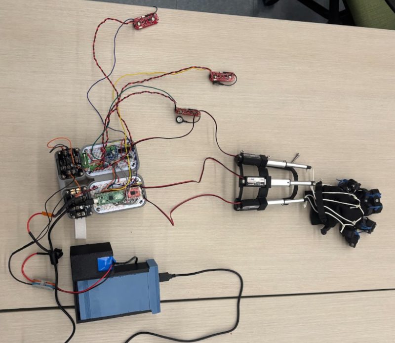
Three linear actuators sit along the forearm and pull cables down to the fingers. Everything else, the Pico and the drivers and the battery, straps on behind them.
WHAT I OWNED
- Three sEMG channels sampled round robin on one ADC, so no muscle waits its turn
- A shared data object living on both cores of the RP2040, handed across as a pointer through the hardware FIFO
- PWM and direction for three linear actuators, with the drivers idled between moves
- TensorFlow Lite Micro running on the second core, with Anna's trained model compiled into the binary
WHY TWO CORES
One core reads the sensors, the other drives the motors. Put both on one core and the signal waits behind the motion, and a grip that lags is a grip nobody trusts.
They share one object. Core zero builds it and passes the pointer across the hardware FIFO, core one catches it and casts it back. From then on both cores are writing into the same place, which is the part you have to be careful about.
16 MHz on the Arduino we started on. 133 MHz and two cores on the Pico.
THE ANALOG PROBLEM
The Pico's own voltage reference was too noisy to measure muscle activation against, and it could not push enough current for three sensors anyway. So the sensors got their own clean three volt line, and that same line went into the ADC reference pin.
A reading is only as good as the thing you compare it against.
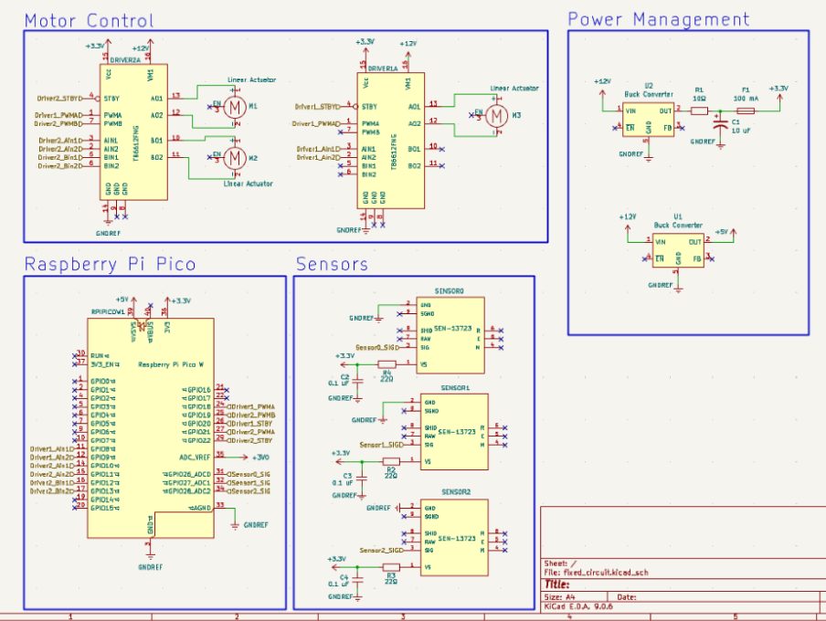
Brandon Spiller's board, in the two sheets the firmware actually cared about. Three sensor channels into GPIO 26, 27 and 28, and the clean three volt line arriving at ADC_VREF on pin 35.
THE GRIPS
The model picks between three grips and two kinds of not moving: open hand, air pinch, full fist, resting, and still resting. Anna Du trained it. My job was getting it onto the chip and turning its answer into motors.
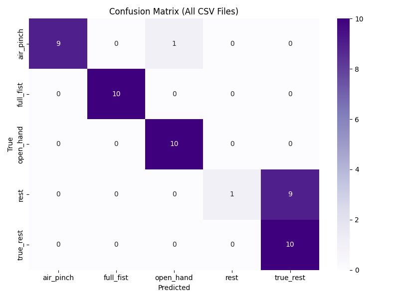
Anna's evaluation of the model. The three grips separate cleanly. The two resting states do not, which is fair, since holding still and holding still look the same coming off a muscle.
WHAT IT NEVER DID
The model path is written and it is not connected. The firmware samples, the classifier has somewhere to put its answer, and the second core runs a fixed sweep instead of the grip it picked.
// instance->get_linear_actuator(0).drive(instance->get_model_value(0));
// insert ml read code
still sitting in main.cpp
WHERE IT LANDED
The device underperformed. One motor driver was carrying two linear actuators, went past what it could supply, and broke. The replacement never shipped, so the build finished on a mismatched pair and reliability went with it.
The current budget was the mistake, and we found it too late to re-spec.
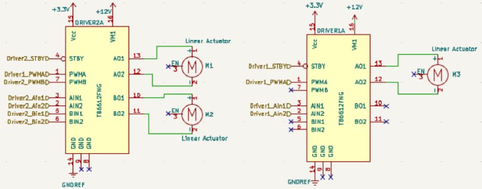
The failure, drawn. The driver on the left has two linear actuators hanging off it and the one on the right has one. That is the current budget problem in a picture.
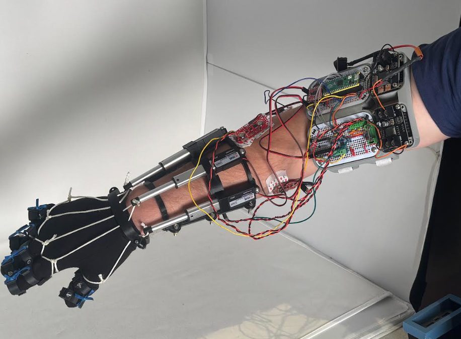
Off the arm and on a table. Two breadboards, three sEMG pads, three actuators, a battery in a printed box, and the amount of wire that takes.